◇ Badge Machine Troubles
A part may be jammed between the Upper Die and the Pickup Die or Crimp Die.
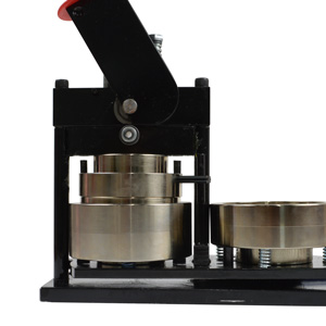
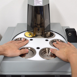
If the rotating table is stuck to the Upper Die and won't move
It is highly likely that a jammed part is the cause, but first, you need to separate the stuck dies to check inside.
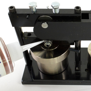
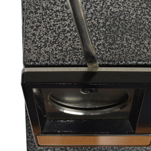
As shown in the video, use a rubber mallet and a wooden stick (or similar object) to gently tap the lower die, taking care not to scratch the machine body.
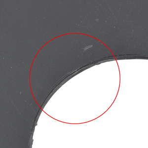
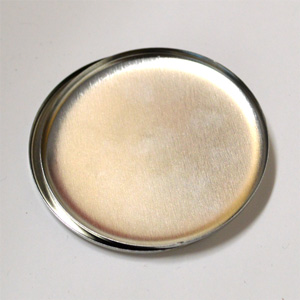
Once the upper and lower dies are separated, look up into the Upper Die (the top die) from below to check if a part is jammed inside.
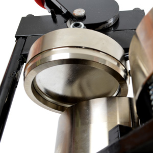
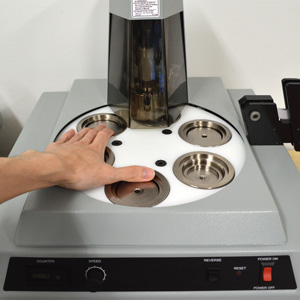
 To remove the jammed part, try lowering the handle gently while the Crimp Die (the one for the back part) is positioned under the Upper Die; this might dislodge it.
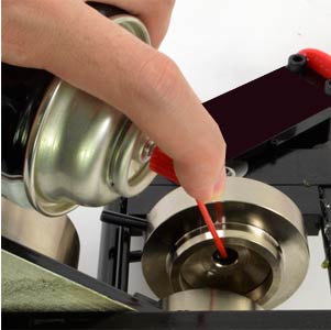
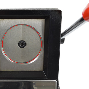
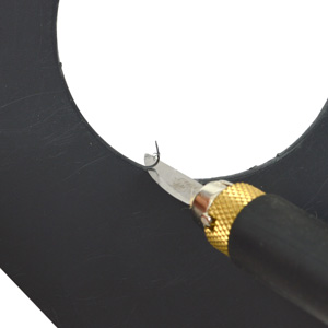
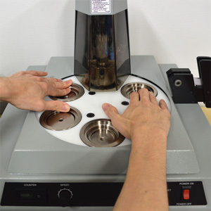
If it doesn't come out, look up into the Upper Die from below and try to hook a part of the jammed component with the tip of a screwdriver or similar tool to pull it out.
Absolutely do not insert a screwdriver or similar tool into the gap between the part and the die. Scratching the die will prevent proper Badge production.
If die replacement becomes necessary during repair, the cost will be very high. If you are concerned, we recommend sending the machine to us for repair instead of attempting removal yourself.
Once the upper and lower dies are separated, look up into the Upper Die (the top die) from below to check if a part is jammed inside.
If it doesn't come out, look up into the Upper Die from below and try to hook a part of the jammed component with the tip of a screwdriver or similar tool to pull it out.
Absolutely do not insert a screwdriver or similar tool into the gap between the part and the die. Scratching the die will prevent proper Badge production.
If die replacement becomes necessary during repair, the cost will be very high. If you are concerned, we recommend sending the machine to us for repair instead of attempting removal yourself.
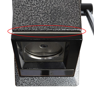
Parts are not jammed, but the handle won't go down / The table won't rotate
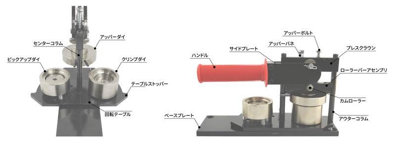
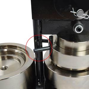
The cylindrical pin with a slit (commonly called a spring pin or roll pin) standing next to the Center Column might have slipped under the horizontally oriented spring pin extending from the Upper Die.
In this state, the handle will not lower. Forcing it down may bend or crush the spring pin, so please refrain from using excessive force.
This can happen if the table is rotated while the outer part of the Upper Die is raised for some reason, but usually, rotating the table resolves the issue by allowing the pin to move back over.
However, in rare cases, this horizontal spring pin can ride over the vertical spring pin and end up on the opposite side, preventing the table from rotating.
If this happens, lift the outer part of the Upper Die while rotating the table to make the horizontal spring pin ride over the vertical one again to the correct side. This should resolve the issue.
◎ Normal State
 The vertical pin is between the two horizontal pins.
The vertical pin is between the two horizontal pins.
× Problematic State
 The horizontal pin is riding on, or has ridden over to the opposite side of, the vertical pin.
The horizontal pin is riding on, or has ridden over to the opposite side of, the vertical pin.
There might be an issue with the paper being used.
Improper paper condition
If the edges of the paper are curled or creased, you won't be able to make clean Badges. Make sure to flatten the paper properly before use.
Also, static electricity causing the paper to stick can hinder successful production. Apply anti-static measures, such as applying silicone spray to the dies, before making badges.
Also, static electricity causing the paper to stick can hinder successful production. Apply anti-static measures, such as applying silicone spray to the dies, before making badges.
Inappropriate paper thickness or material
If the paper used for the artwork is too thick, it cannot be crimped properly, leading to a higher failure rate for Badges.
The recommended paper thickness for use with the Badge machine is 0.1mm to 0.15mm.
There might be slight variations depending on the badge size, so please refer to the chart here.
Also, please note that production may not be possible with special types of paper, such as vinyl-coated paper or paper with extremely poor slip properties.
Similarly, we do not recommend using non-paper materials like fabric, cellophane, or leather for production. Please understand that we cannot provide any warranty against malfunctions or troubles resulting from the use of such materials.
The pin position might be incorrect, or dust/debris might be attached to the paper and film.
Incorrect pin position
When using back parts with double hook pins, if the pin is attached incorrectly or shifts to an improper position during pressing, the area where the pin makes contact might appear slightly raised on the front side.
Ensure the pin is attached correctly in the proper position before production.
Debris attached to paper or film
If debris is attached to the paper or film being used, it can get trapped between the paper and film when the parts are pressed, causing the film to appear raised.
Even very small debris like dust can significantly affect the appearance of the finished product, so be very careful to prevent debris from entering during production.
Film is particularly prone to attracting debris due to static electricity, so handle it carefully, taking out only the amount needed for immediate use.
Dirt on the machine or cutter can also be a source of debris, so we recommend regular cleaning and maintenance.
Please try the following three steps.
Is the thickness and type of paper used appropriate?
Please check if you are using paper of the recommended thickness and type. Using special paper, or paper that is too thick or too thin, may prevent successful production.
First, try changing to the appropriate paper. For recommended paper specifications, please see the chart here.
First, try changing to the appropriate paper. For recommended paper specifications, please see the chart here.
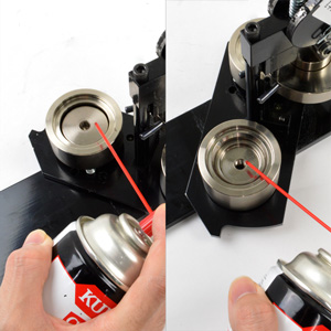
Perform die maintenance by applying silicone spray
Apply silicone spray to the Crimp Die, Pickup Die, and Upper Die, then wipe off any excess oil with a clean cloth.
Doing so removes small debris like adhered dust and prevents defects caused by static electricity.
Doing so removes small debris like adhered dust and prevents defects caused by static electricity.
Try making a badge with paper that has no ink printed on it
The ink itself can sometimes interfere with proper production. Try making a Badge using blank paper with no printing.
If production is successful with blank paper, next try adjusting the design so that ink is not printed on the area that gets crimped inside the back part.
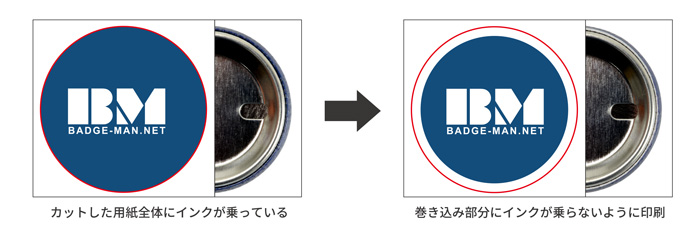 If production is successful in these two patterns, it's highly likely that the ink is the issue. Be aware that this problem tends to occur more often when using dark background colors (which use a large amount of ink).
If production is successful with blank paper, next try adjusting the design so that ink is not printed on the area that gets crimped inside the back part.
If the problem persists after trying all the above steps, repair or maintenance may be necessary. Please contact our Customer Service.
Machine operational issues or inability to make clean Badges may be resolved by performing maintenance.
Maintenance using silicone spray and machine lubricant
Perform maintenance using the appropriate oils as shown in the image below.
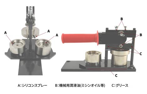
For the Pickup Die and Crimp Die, spraying from above is sufficient. However, the Upper Die needs lubrication on its downward-facing side, which can be a bit tricky. Look up from below and spray carefully.
 When applying grease to the Rotating Table, slightly shift the table and apply from underneath rather than onto the Base Plate side to prevent excessive spreading.
Apply grease between the Roller Bar Assembly and each Column by working it into the gap from the side.
Use a fine-tipped oiler (like for sewing machines) to apply small amounts of machine lubricant (sewing machine oil, etc.) to the designated parts.
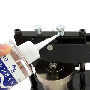
 Do not drip machine lubricant like sewing machine oil onto the die parts (Pickup Die, Crimp Die, etc.). Oil other than silicone oil can cause contamination and interfere with Badge production.
Apply a small amount of silicone spray to (A) the Upper Die, Crimp Die, and Pickup Die. Wipe off excess oil with a clean cloth, spreading it evenly over the entire die surface.
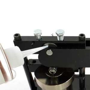
Apply machine lubricant such as sewing machine oil to (B) the Cam Roller, the gap between the Side Plate and Press Crown, and the Upper Bolt insertion point. After application, perform several empty cycles to work the lubricant into the machine.
Apply grease to (C) the area between the Base Plate and Rotating Table, and between the Roller Bar Assembly and the Outer/Center Columns.
For the Pickup Die and Crimp Die, spraying from above is sufficient. However, the Upper Die needs lubrication on its downward-facing side, which can be a bit tricky. Look up from below and spray carefully.
Apply grease between the Roller Bar Assembly and each Column by working it into the gap from the side.
Use a fine-tipped oiler (like for sewing machines) to apply small amounts of machine lubricant (sewing machine oil, etc.) to the designated parts.
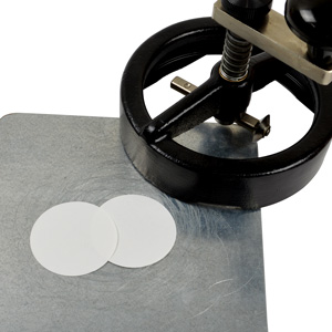
◇ Professional Circle Punch Cutter Troubles
A foreign object might be jammed between the blades.
Return the blade to its original position and remove the foreign object
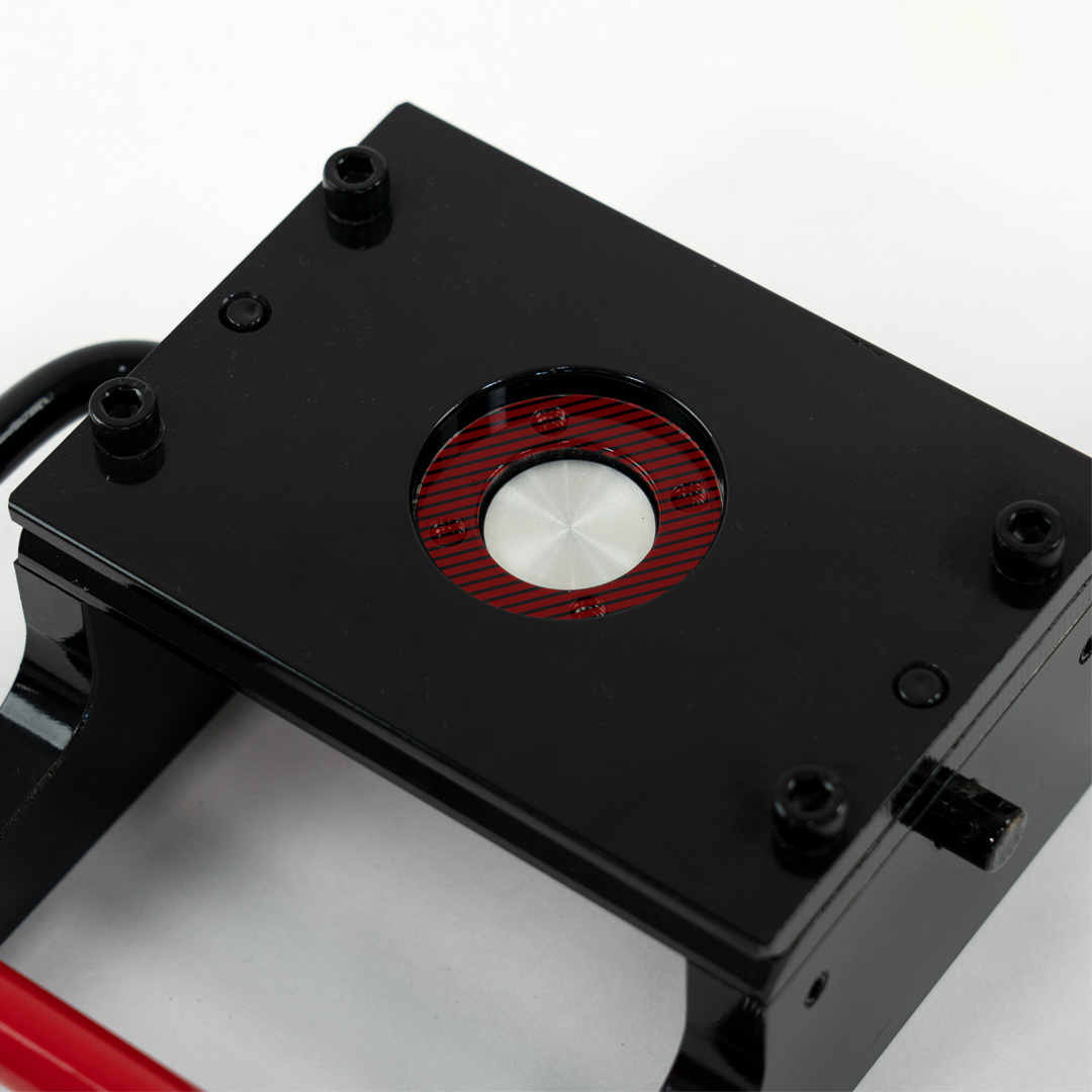
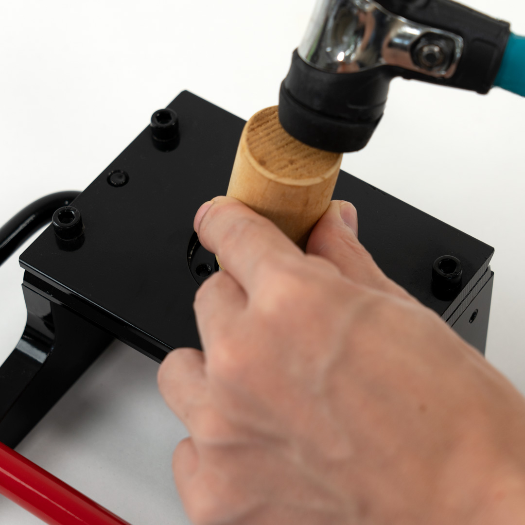
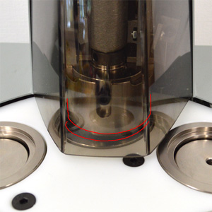
First, push down the blade part (the red part in the first photo) visible through the opening on the top plate with your finger to return it to its original position.
If you cannot push it down with your finger, use a rubber mallet or a piece of wood as a buffer to gently tap it down, being careful not to damage the cutter body.
Once the blade is back in position, use an air duster to blow air into the gap between the blades to remove the jammed foreign object.
If performance issues persist after removing the object, performing simple maintenance might improve the situation.
Are you trying to cut something other than paper?
This product is not compatible with materials other than paper
The cutter is designed for paper only and is not compatible with materials such as fabric, leather, or materials using special fibers.
We cannot provide any warranty for troubles or damages caused by using materials other than paper.
If the cutting performance has degraded through normal use, first try performing maintenance.
If it still doesn't cut cleanly, blade sharpening is possible, but this requires sending it to our factory in the US, which will take a considerable amount of time.
Reduced cutting performance or operational issues may be improved by performing maintenance.
Maintenance using silicone spray and machine lubricant
Perform maintenance using the appropriate oils as shown in the image below.
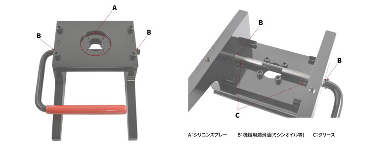
Apply (A) silicone spray to the contact area of the front cutter blade after removing any debris. After application, cut some scrap paper several times to remove excess oil until it no longer transfers to the paper.
Apply a small amount of (B) machine lubricant to the handle insertion points on both sides.
Apply (C) grease thoroughly and widely to the contact area between the plate and handle on the backside.
◇ Stand Cutter Troubles
Is the plate at the paper insertion slot tilted forward or backward?
Return the insertion slot plate to its original position
The stand cutter has paper insertion slits on the top and sides.
If you press down on this area with your hand while cutting, the plate can bend, narrowing the insertion slot.
If you press down on this area with your hand while cutting, the plate can bend, narrowing the insertion slot.
When the plate is bent like this, the alignment between the opening in the plate and the rising cutter blade can become poor, causing them to contact before the blade passes through the opening.
This can cause symptoms like the handle not moving.
This can cause symptoms like the handle not moving.
To resolve this, the plate needs to be returned to its original position.
Insert a flathead screwdriver or similar tool into the insertion slot and gently bend it forward or backward to adjust the width of the slot.
Insert a flathead screwdriver or similar tool into the insertion slot and gently bend it forward or backward to adjust the width of the slot.
Are you trying to cut something other than paper?
This product is not compatible with materials other than paper
The cutter is designed for paper only and is not compatible with materials such as fabric, leather, or materials using special fibers.
We cannot provide any warranty for troubles or damages caused by using materials other than paper.
The stand cutter is not covered by warranty. Therefore, even if cutting performance degrades through normal use, we cannot offer repair or replacement services.
We cannot provide any warranty for troubles or damages caused by using materials other than paper.
The stand cutter is not covered by warranty. Therefore, even if cutting performance degrades through normal use, we cannot offer repair or replacement services.
◇ Rotary Circle Cutter Troubles
Have you selected the correct cut size?
Please double-check the guide hole used for size adjustment
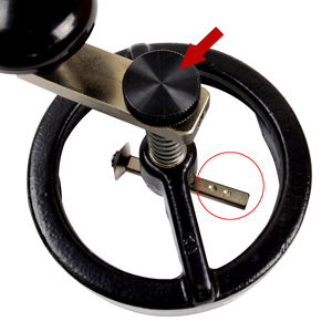
The rotary circle cutter allows changing the cut size by adjusting the length of the bar extending horizontally from the center.
This bar has guide holes for setting four different sizes. Following these allows for correct size cutting.
If the size is incorrect, it's highly likely that the setting is misaligned. Try setting it carefully according to the guide hole.
※ To adjust, loosen the knob at the top center to change the bar's position.
The position of the template opening might be misaligned.
Adjust the position or size of the opening
The plastic template set into the body can experience slight positional shifts due to its nature. Over time, the blade and the template opening might become misaligned.
If this happens, the blade might ride onto the template during rotation, preventing parts of the paper from being cut.
If this happens, the blade might ride onto the template during rotation, preventing parts of the paper from being cut.
To resolve this, you need to use a cutter or craft knife to shave away parts of the opening until the blade no longer rides on it.
※ Widening the opening too much might make it difficult to align accurately when cutting out paper designs.
However, as this is a basic cutter, we recommend using the Professional Punch Cutter for precise cutting needs.
※ Widening the opening too much might make it difficult to align accurately when cutting out paper designs.
However, as this is a basic cutter, we recommend using the Professional Punch Cutter for precise cutting needs.
The inability to cut cleanly might be due to the blade's sharpness rather than the template.
Try cutting paper without the template attached. If it cuts properly, the blade is fine, and you should adjust the template.
If it still doesn't cut, the blade currently in use is likely the problem. Please purchase a replacement blade here and replace it.
Try cutting paper without the template attached. If it cuts properly, the blade is fine, and you should adjust the template.
If it still doesn't cut, the blade currently in use is likely the problem. Please purchase a replacement blade here and replace it.
◇ Auto Badge Machine Troubles
The safety feature might have activated and stopped the machine due to overload from a jammed part.
If the machine suddenly stops during production, a jammed part is the most likely cause. Remain calm and follow the steps below carefully to resolve the issue.
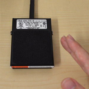
Check the Reset Light and restart
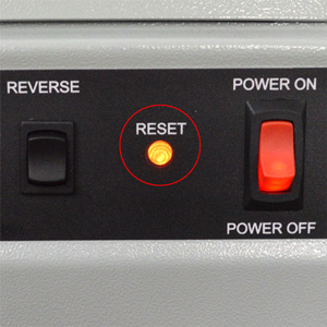
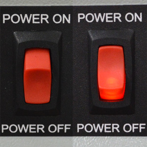
If it's flashing, it means the machine has detected an overload and automatically stopped.
It cannot operate in this state, so turn the power OFF, then turn it back ON to restart the machine.
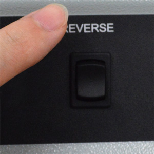
Recovery using reverse rotation
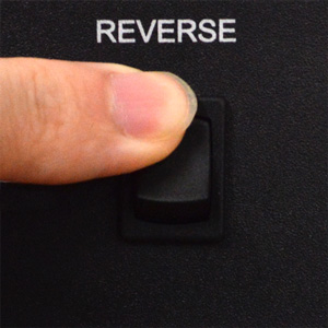
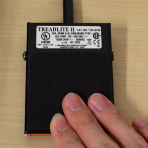
In that case, first press and hold the Reverse Switch on the main body, then press and hold the Foot Switch. This will reverse the motor rotation and lift the Upper Die.
Remove the jammed part
In that case, place both hands on the Die Table and manually rotate the table counter-clockwise to retrieve the part.
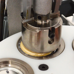
If the part does not fall out during the reverse operation, remove the Upper Die from the machine body and clear the jammed part from inside it.
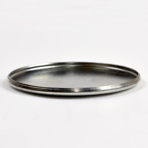
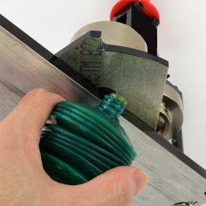
※ Jamming often occurs when two shells are stacked and pressed together (as shown in the photo). Also, using paper thicker than the recommended specification increases the pressure sensed by the machine, which might unexpectedly trigger the safety feature.
Regarding part stacking, besides shells, the collets on back parts can easily stack unnoticed, so pay close attention during operation.
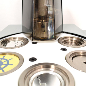
The Die Table might be starting up from an incorrect initial position.
To check, manually rotate the Die Table. If it spins with only light resistance using one hand, the position is likely incorrect. The correct initial position is when you feel significant resistance (requiring some force with both hands to turn) in both forward and reverse directions when either the Crimp Die or Pickup Die is directly under the Upper Die.
Even if the position seems correct, always rotate the table at least once to check that all movements are functioning normally.
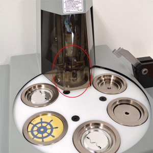
Press pressure adjustment might be necessary.
Adjusting the press pressure
First, perform simple maintenance like applying silicone spray. If the issue persists, follow the steps below to adjust the pressure.
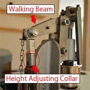
First, remove the machine cover and locate the part shown in the left photo at the rear of the machine body.
By moving this component called the 'Height Adjusting Collar' up or down, you adjust the lift amount of the 'Walking Beam', thereby changing the press pressure.
When adjusting pressure, you generally only need to touch this part. Do not loosen other bolts or screws, as this could cause malfunctions.
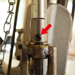
When viewed from directly behind the machine, the approximate initial position has a gap of less than 1mm between the Height Adjusting Collar and the silver component above it, with the set screw (grub screw) centered.
Loosening this set screw allows height adjustment.
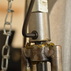
Use the hex wrench (1/8 inch) included with the automatic machine to loosen it, then turn the Height Adjusting Collar left or right to adjust the height.
Moving it upwards decreases pressure, while moving it downwards increases pressure.
The adjustable range is not very wide, so lowering it all the way down generally won't cause excessive pressure. However, this assumes the use of recommended paper. Be cautious if using paper exceeding the specified thickness.
Check the position of the Speed Control Dial
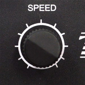
If the dial is turned fully counter-clockwise, the machine will be completely stopped. Turn the dial slightly clockwise to increase the speed and try operating it.
If it still doesn't move, a part might be jammed. Please check the section Machine stopped mid-production. If the problem isn't resolved, please contact Customer Service.
If it still doesn't move, a part might be jammed. Please check the section Machine stopped mid-production. If the problem isn't resolved, please contact Customer Service.
The battery might be dead.
The Part Counter has an independent power source, and its battery typically lasts 3-4 years.
Battery replacement is only permitted by authorized service personnel. If the battery runs out, please contact our Customer Service.
Battery replacement is only permitted by authorized service personnel. If the battery runs out, please contact our Customer Service.
Please contact our Customer Service.
tel: 0575-65-5311 (Reception hours: Weekdays 9:30 AM - 5:00 PM JST)
fax: 0575-67-9210
e-mail:[email protected]
[Regarding Repairs]
For repairs of badge machines or cutters, please submit a prior application using the repair request form.
Please note that we cannot accept repairs for items sent without prior notification.
fax: 0575-67-9210
e-mail:[email protected]
[Regarding Repairs]
For repairs of badge machines or cutters, please submit a prior application using the repair request form.
Please note that we cannot accept repairs for items sent without prior notification.


![Semi-Auto Badge Machine [KSA10000]](images/webp_images/KSA10000.webp?v=1779257788 "Semi-Auto Badge Machine [KSA10000]")
![44×70mm 丸角長方形 Die Set for Semi-Auto Badge Machine [KSA10000]](images/webp_images/coming_soon.webp?v=1773901694 "44×70mm 丸角長方形 Die Set for Semi-Auto Badge Machine [KSA10000]")


